Can someone please show me a picture of wire diagram in the throttle acuator control module or throttle position sensor for 07 Hyundai santa fe
I can’t figure what color wires are?!
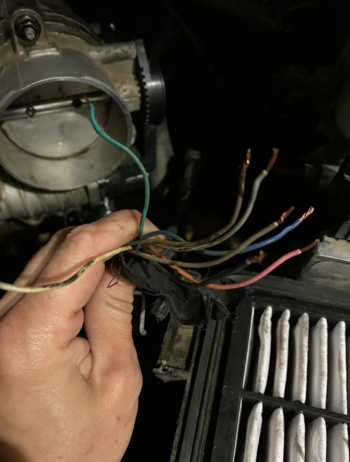
I accidentally yanked them lose trying to get the module disconnected.
I had to redo it anyways because that’s where my problem lies, but dumb me got frustrated and yanked on it!
1 Like
I understand your frustration—it can be really stressful to fiddle with wires, especially when it comes to car components. Thankfully, you should be able to locate a wire diagram for your 2007 Hyundai Santa Fe throttle position sensor (TPS) without too much difficulty.
Here’s a step-by-step guide on how to find the throttle position sensor on most vehicles:
- Find the throttle body, which is typically a cylindrical component linked to your air intake and engine block via a large hose.
- Look for the TPS mounted on the throttle body, identifiable by a small sensor with a connector that plugs into it.
To locate a wiring diagram, you can usually perform an online search for “2007 Hyundai Santa Fe throttle position sensor wiring diagram” or refer to a repair manual specific to your vehicle.
Below is an image that may be useful, although it might not be specific to your car model:
I know how hard it can get when repairing doesn’t go as you planned.
@Maverick For your 2007 Hyundai Santa Fe, it’s crucial to correctly reconnect the throttle actuator control module and the throttle position sensor.
Here’s a simple way for on-the-wire color for the Electronic Throttle Control (ETC) system:
- Yellow wire to pin 1 on the motor connector.
- Green wire to pin 2 on the motor connector.
- Blue/Black wire to pin 3 on the motor connector.
For the Throttle Position Sensor (TPS), the typical wire connections are:
- Grey and Pink wires for the 5V supply.
- Brown and Black wires for the 12V supply.
- Brown and Green are grounds.
- Blue and White are for the 8V supply.
It’s best to check a repair manual or consult a professional to ensure accurate connections.
Here is the Image of the 8pin TPS module COLOR WIRE DIAGRAM